Beaumont Technologies, Inc. (BTI) was founded in 1998 and is headquartered in Erie, PA. BTI is the industry leader in the development and application of rheological control systems. Though BTI provides a unique mix of products designed to optimize the efficiencies of the mold and the injection molding process, its focus is on the optimization of the melt delivery system and its impact on the molding process and resultant molded part quality. (Source:Beaumont Technologies, Inc. https://www.beaumontinc.com) In any single part of multi-cavities mold, there is still a problem of an intra-cavity imbalance that possibly results in part inconsistencies from cavity to cavity even though flow to each cavity is balanced. Through Moldex3D CAE tool, we can easily visualize the imbalanced phenomenon and verify the availability of MeltFlipper® MAX™. The combination of Moldex3D and MeltFlipper® MAX™ not only can detect the cause of intra-cavity imbalance flow but also can solve the filling imbalance problem easily and properly. Over one decade of involvement in plastics industry as his career and study, David A. Hoffman has made the plastics processing much easier, more creative, and more innovative. So far he has worked as the Global Director of Technical Sales & Marketing in Beaumont Technologies, Inc (BTI), the leading provider of mold and process optimization technologies. CoreTech and BTI have established a reliable relationship based on technical cooperation. We can see any single parts in multi-cavities mold may still experience an intra-cavity imbalance, which may cause part inconsistencies from cavity to cavity, even though flow to each cavity is balanced. There are two basic options to solve this problem. The first option is to add one additional melt rotation to control the position of the high sheared material within the part in order to force those laminates to flow through the center of each cavity. The second option is a new-patented melt-management technology – MeltFlipper® MAX™ that provides symmetry of high sheared laminates in multiple axes. This technology provides for more homogeneous melt condition to enter into a cavity. In injection molding application, this latest innovation may help prevent core shift, help increase flow lengths for thin walled applications, and provide the ability to manipulate and manage the melt flow front within a part (Fig.1). Melt-management technologies as discussed here may be used to address both cavity-to-cavity or intra-cavity imbalances within any given mold, either low cavitation or high cavitation, hot runner or cold runner. Through Moldex3D CAE tool, we can easily visualize the imbalanced phenomenon and verify the availability of MeltFlipper® MAX™. Figure 2 and 3 have illustrated the examples of a single cavity mold and each of them is an A-type single mold. With a single cavity mold, there cannot be any cavity-to-cavity imbalances since there is only one cavity. But the non-desirable flow front in the single cavity is the problem in these cases, which is solely due to the shear imbalance creating non-uniform material properties within the cavity. In A-type mold, it usually results in a weaker welding line at center of sample. By understanding shear and flow of plastics, a designer can now begin to apply melt-management technologies in the initial mold design stage based on certain part geometry and number of cavities. Melt-management technologies also help eliminate the manual inspection and sorting costs required from customer rejects or day-to-day molding scrap, thus allowing companies to replace their inspectors and put producers in their place (Fig. 4). Moldex3D can help people know how the intra-cavity imbalance flow happened, and MeltFlipper® MAX™ can solve the filling imbalance problem easily and properly. CoreTech and BTI have established a reliable relationship based on the technical cooperation. We have been the exclusive reseller of MeltFlipper in Great China and Taiwan. For more information about MeltFlipper® MAX™ technology, please contact CoreTech or BTI directly. * This case was published in March, 2006. Moldex3D News No. 14 Best PVC vertical injection molding machine, Efficient plastic injection blow molding machine, injection molding auxiliary equipment, Automatic molding machine plastic price NINGBO HAITUO MACHINERY TECHNOLOGY CO.,LTD , https://www.china-haituo.com![]()
Challenge
Solution
Benefits
 David holds an Associate Degree in Mechanical Engineering Technology and a Baccalaureate Degree in Plastics Engineering Technology from Penn State University. He is the author of various published ANTEC papers. He also worked as the Engineering Manager for an automotive supplier of high precision plastic components and assemblies for years. Later he started working for BTI until now. While at Beaumont Technologies, he has co-invented the company’s second patent along with John Beaumont on a next generation MeltFlipper® MAX™ Technology, known as MeltFlipper® MAX™, which is capable of re-establishing multi-axis material property symmetry within the melt channels and cavities of cold and hot runner molds. CoreTech and BTI aim at introducing their techniques to local users who desire CAE simulation analysis or runner design optimization for better productions. In any single part of multi-cavities mold, there is still a problem of an intra-cavity imbalance that possibly results in part inconsistencies from cavity to cavity even though flow to each cavity is balanced. Now, a new-patented melt-management technology- MeltFlipper® MAX™ presented by BTI can provide symmetry of high sheared laminates in multiple axes.
Flaws existed in the original runner design
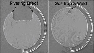
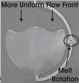
Fig. 1 Â (a) Rivering flow front due to intra-cavity imbalance in a single cavity mold
Fig. 1 Â (b) Modified and controlled flow front using melt-management technologies
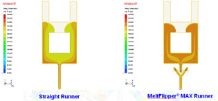
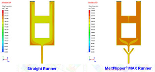
Fig. 2 Temperature distribution of 70% filling melt front in an A-type mold. (L)original runner design (R) with MeltFlipper® MAX™ runner design
Fig. 3 Temperature distribution of filling end melt front in an A-type mold. (L) original runner design (R) with MeltFlipper® MAX™ runner design
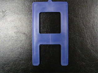
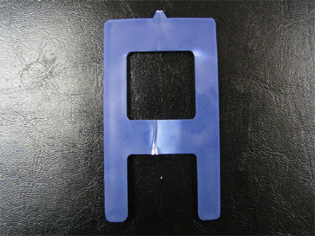
Fig. 4 Â (a) Weld line formed by cold melt which results in brittle fracture
 Fig. 4  (b) Weld line formed by hot melt which results in ductile fracture
Double win
BTI and Moldex3D Provide The Most Advanced Solutions For Runner Design
Customer Profiles