Thermal Cycling Tests (TCT) are important reliability test items in IC industry. They are used to assess whether a product can maintain its quality throughout the design cycle amid fluctuating temperatures. TCT procedure involves placing packaged product in a controlled temperature environment and subjecting it to a series of high and low temperature changes at a rate of 5 to 15 degrees per minute. The most common failure modes arise from significant differences in the coefficient of thermal expansion (CTE) among the product’s internal components, leading to repeated thermal stress at the interface and the accumulation of residual stress during cooling cycles. These stresses eventually cause delamination between components, component fractures, or the most common solder crack. In practice, the process from designing, mold opening, packaging, to actual thermal cycling tests often requires a substantial amount of time, manpower and resources. Therefore, using computer simulations to perform thermal cycling tests and using thermal cycle time as a reference for design modifications and design optimization have become a critical issue to accelerate overall procedure and reduce development cost. To simulate Thermal Fatigue phenomenon, numerous studies have proposed thermal fatigue models, which can be classified into three categories based on the physical quantities used in the model: stress-based, strain-based, and energy-based models. Among these, the strain-based Coffin-Manson Model is the most widely used for predicting low cycle thermal fatigue (Wang et al., 2017). The cycle prediction model of the Coffin-Manson Model is: This model utilizes the material ductility coefficient  Thermal fatigue coefficient can include material fatigue ductility coefficient In this model,  This study below utilizes PMC (post mold curing) solver of Moldex3D Stress analysis that considerate material nonlinearity and analyze the effect from the entered temperature variation through time in a thermal cycle test. Estimate plastic equivalent strain through plastic strain Prandtl-Reuss model and material uniaxial yield stress and von mises stress. Output the average temperature, cycle frequency information from this simulation results. With modified Coffin-Manson model, the number of cycles can be estimated. Utilizing post mold curing solver in Moldex3D, which considers material viscoelasticity, input environmental temperature and corresponding time in thermal cycle test calculates stress distribution that changes through time and temperature in TCT test. Record the location of thermal fatigue based on the maximum von mise stress value in the stress distribution. Estimate equivalent amplitude of plastic strain by analyzing at the point based on the stress over time. Finally, predict cycle times required to reach thermal fatigue under same condition by Thermal fatigue model. The currently adopted thermal fatigue and plastic strain models are widely applicable for analyzing simple mechanical behavior of metallic materials. However, the parameters in the utilized models still need to be obtained through more complete experiments. In the future, users can select more appropriate models for their chosen materials and utilize verified material parameters to feedback precise cycle prediction value for user’s reference. Modlex3D will continuously optimize the solver kernel and workflow to better integrate CAE reliability analysis, thereby accelerating the product cycle. Ultra-high Pressure Supercharger design of ultra high pressure valve, hydraulic ultra high pressure valve Chuntian Machinery Technology Co., Ltd , https://www.hpppower.comStan Chung, R&D Engineer at Moldex3D
Introduction
Thermal Fatigue ModelÂ

 , amplitude of plastic strain
 and fatigue ductility exponent
 to predict the fatigue cycle number
 . Fatigue ductility exponent can be obtained through the Modified Coffin-Manson Model:
 is average temperature per cycle and
 is the average frequency per cycle (Cycle/day)
Equivalent Plastic Strain ModelÂ
 , which can be obtained from tables or experiments, as well as the cycle temperature
 and cycle frequency
 from thermal cycle tests being simulated. Fatigue ductility coefficient
 , which is more challenging to directly acquire from solid mechanics analysis, can be estimated by analyzing material properties and finding corresponding plastic strain models. For metal IC components that are more prone to thermal fatigue, such as solder ball, lead frame, their plastic behavior can be calculated through the Prandtl-Reuss Model considering Isotropic-hardening
 represents uniaxial yield stress,
 is plastic equivalent strain,
 indicate reference strain component,
 refers to von Mises stress,
 is non-dimensional material constant and
 represents power-law hardening exponent. This model is more suitable for cases where the repeated loading in each cycle does not reach the plastic deformation of the specimen, thus preventing permanent deformation.
Simulation of Thermal Cycling Test

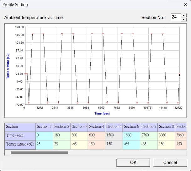
Fig 1. Ambient Temperature settings in post mold curing
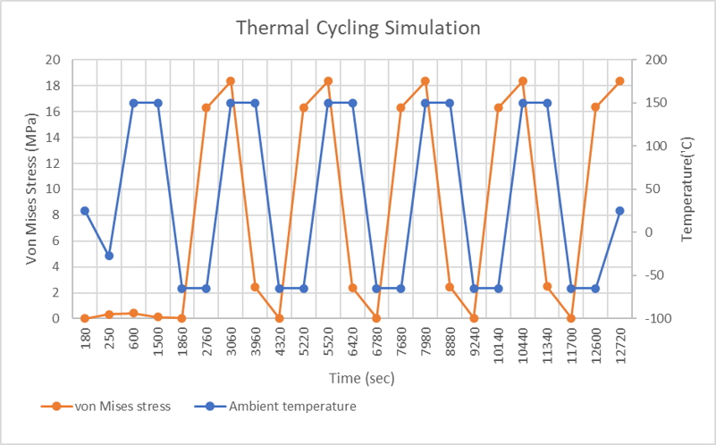
Utilizing the point of maximum von mises stress of each cycle as the observation for thermal fatigue, the relationship between setting temperature and von mises analysis results is plotted as below:
Fig 2. Internal Stress and Temperature Variation with Ambient TemperatureConclusionsÂ