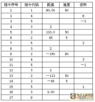
1 Introduction Double-head CNC lathes are non-standard CNC lathes and are special machine tools. According to the specific technical conditions of the use unit, the customer adopts Delta's electromechanical integration technology application program to effectively control equipment costs and meet the application requirements of end users. The main feature of the double-head CNC lathe is the use of double-spindle heads for bi-directional machining of workpieces. Compared with the one-way machining process of traditional lathes, the double-head CNC lathes realize bidirectional machining and the theoretical machining efficiency is doubled. For the batch machining of disc sets and short shafts (without tail stock) that require high coaxiality for secondary positioning, the CNC precision automatic double head lathe is an efficient and even the only processing equipment. Double-head CNC lathes include left and right slide pedestals, left and right large carriages, left and right longitudinal ball screws, left and right longitudinal servo motors and numerical control devices. Between the left and right sliding pedestals, there is a main shaft seat which is fixedly connected with the main shaft seat. The main shaft seat is provided with a hollow main shaft, a transmission box and a variable frequency motor, and horizontal left and right intermediate drag boards are arranged on the left and right large drag boards. Supporting left and right lateral ball screw pairs and left and right transverse servo motors are provided. 2, system design 2.1 Technical Analysis of Control System The main purpose of the double-head CNC lathe in this case is to pursue the processing efficiency, and the process is relatively simple. The large pallet can be moved freely longitudinally, the left spindle box starts, the large pallet fast forward moves to the left, and after entering the position, it becomes a work knife. After machining, the spindle motor stops running, and immediately brakes. The electromagnetic brake is applied to the spindle. The spindle stops instantly. The large pallet drives the guillotine blade to exit quickly. After the right position is reached, the spindle motor stops and the right spindle motor starts. Moving to the right, after entering the position, it becomes a worker knife, after the spindle is in position, the spindle motor stops running, the electromagnetic brake brake operates, the spindle momentarily brakes, the large pallet drives the guillotine blade to quickly withdraw into place, waiting for the next machining action, and a back and forth machining cycle At the end, the next cycle continues to work, and the cycle continues until the end of the entire work process is reached by pressing the stop button, and the equipment is shut down. The workpiece fixture is a hydraulic chuck with an under pressure alarm display to alert the user. 2.2 Equipment Electrical Control Scheme Considering that the equipment of this case does not have very strict requirements on processing accuracy, a relatively economical control system solution has been formulated. The schematic diagram of the principle composition of the electric control system for the double-head CNC lathe based on Delta's automation platform is shown in Figure 1. 2.3 Control System Implementation (1) CNC system: Delta PUTANCA2P-1, one. 3, Delta A2P system debugging According to the actual operating conditions of the equipment, JOG (manual) mode estimates the servo load inertia ratio, according to the value, using the servo gain calculation software to debug the servo gain, repeated testing, adjusted to the appropriate state of the processing accuracy. The inverter sets the relevant parameters, and the speed and running commands are provided externally. The A2P CNC system user program is not the same as other CNC products. It is similar to the form of an electronic form. The final program is as follows: 4 Conclusion The technical solution of this case is relatively easy to implement. This article does not highlight technological innovation. It is only through this article that it demonstrates the advantages of Delta DELTA electromechanical products in terms of electromechanical integration solutions and cost-effectiveness. It can meet customers’ actual technical requirements and try to provide customers with Saving economic costs also provides reference and reference experience for other users to apply Delta's mechanical and electrical products to achieve control system requirements. Universal Car DVD/GPS Co., Ltd. , http://www.flow-toyotacardvd.com
Fig. 1 Electric Control System of Double CNC Lathe
The upper controller adopts Delta A2P-1 single-axis controller, which is of low cost and is completely suitable for customer's application. The CNC sends pulse command to the servo driver to implement precise positioning requirements. The large pallet operation is controlled by the servo system. Taking into account the actual needs of large pallet operation inertia, we chose Delta A series 3.0KW medium inertia servo motor to provide sufficient power source. Spindle motor 5.5KW, selected two Delta B series AC frequency converter, the spindle speed reached 3000RPM, real-time display of motor speed through the inverter digital operating panel, motor frequent start, electromagnetic brake stop. Frequency command source external potentiometer knob, according to different parts of the processing requirements of manual speed. The inverter running command is controlled by the relay contact and the CNC system outputs the switch command.
(2) Servo driver: Delta ASD-A3023MA, one.
(3) Servo motor: Delta ASMT-30M250AK, 1 set.
(4) Inverter: Delta VFD055B43A, 2 sets. 