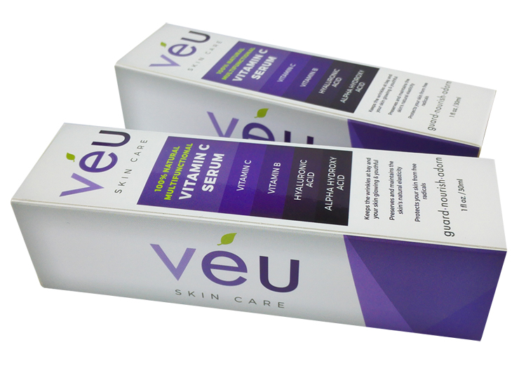
With the development of B2B websites, merchandise a variety of products, in addition to good quality, but also need the right taste exquisite packaging, especially in an age of branding. So fine cosmetic box play an important role in value-added.
Our coesmetic box make great effect on promotion in a large extent. It has eye-catching design, innovative design of the structure, vibrant colors, beautiful patterns clear. So that consumers see the cosmetic packing box while it will have a very strong desire to buy your cosmetic. Then would you be interested in our cosmetic boxes?
There are eyelashes box, hair box, lipstick box etc.
*Related Products:perfume box,perfume packaging.
If yes, let us approached exquisite cosmetic boxes:
The customized sizes are available.
The elegant structure design can be chosen.
Give the most suitable material according to our experience of the cosmetic box
4. The cosmetic box with high quality printing.
5. Great special handling. (Hot stamping, Spot UV, Embossing)
Paper Cosmetic Case,Daily Chemical Products Box,Cardboard Packaging Cosmetic Box Guangzhou Mingyin Packaging Trading Co.,Ltd. , https://www.mypaperpackages.com
1, the main problems and failures
(1) The qualification rate for drawing is relatively low, about 55%, unable to meet the process requirements. The phenomenon is often the cracks of the pressed and drawn parts.
(2) The pressing speed of the upper hydraulic cylinder (master cylinder) cannot be adjusted, so it cannot meet the pressing process requirements of some varieties.
(3) Pressure adjustment is inconvenient and has low accuracy and poor stability, which reduces system reliability.
(4) Unstable operating speed, high vibration, and high noise.
2, the cause of the failure analysis
2.1 The original hydraulic system works 
Fig. 1 Hydraulic system before reconstruction
The working process of the hydraulic cylinder is as follows:
(1) The hydraulic cylinder 9 descends quickly. The IYA is energized, the reversing valve 5 is switched to the left position, and the oil inlet is: the pump 1 → the check valve 4 → the reversing valve 5 left position → the hydraulic check valve 6 → the hydraulic cylinder 9 upper chamber. At the same time, the pilot-controlled check valve 7 is open, and the master cylinder piston accelerates downwards under the action of the gravity of the slider. The pump is not fed with oil and the negative pressure in the upper chamber causes the hydraulically-controlled check valve 8 to conduct, and the oil in the oil-filled tank enters. The upper cavity of the cylinder 9 is filled with oil. Return to the oil: hydraulic cylinder 9 lower chamber → hydraulic control check valve 7 → reversing valve 5 left position → reversing valve 12 neutral → fuel tank.
(2) The master cylinder slows down. When the upper slider touches the workpiece during operation, the pressure in the upper chamber increases, and the valve 8 closes. At this time, the pressure slow down speed is determined by the flow rate of the hydraulic pump. Its inlet and outlet circuits are the same as those in the fast down stream.
(3) Maintain pressure. When the pressure in the upper cavity of the master cylinder rises to the set pressure of the pressure relay 15, the signal is sent to make 1YA deenergized, and when the reversing valve 5 is switched to the neutral position, the upper and lower chambers of the master cylinder are closed and maintained pressure. The pressure holding time is adjusted by the time relay according to the process requirements. At this point the pump is unloaded.
(4) Quick return. When the holding time is up, the time relay sends a signal to energize 2YA, and the reversing valve 5 switches to the right position. The oil inlet is: pump 1 → valve 4 → valve 5 (right position) → valve 7 → master cylinder 9 lower chamber. At the same time, the valve 8 and the valve 6 are turned on, and the oil returns all the way back to the oil-filled tank, and the other route is the master cylinder upper chamber→valve 6→valve 5 (right position)→valve 12→oil tank. The working process of the ejector cylinder (lower cylinder) is as follows: When the master cylinder returns to the upper position, the 3YA is energized, the valve 12 is switched to the right position, and the ejector cylinder is upwardly ejected. Its oil inlet is: pump 1 → valve 4 → valve 5 (center) → valve 12 right → top cylinder 11 lower chamber. Return to the oil: cylinder 11 upper chamber → valve 12 → fuel tank. In addition, the ejector cylinder can stay in position when the 3YA power is off. When the sheet is stretched and pressed (floating blanking), when the ejector cylinder is maintained at a certain pressure in the upper position and the master cylinder slider is lowered, the oil return path is as follows: the overflow chamber of the ejector cylinder 11 overflows. Valve 13, tank.
2.2 Problems in the original hydraulic system
The major problem of vibration and noise occurs mainly during the rapid descent of the master cylinder and the commutation return after the dwell pressure. There are two main reasons for the analysis:
(1) There may be a constant opening and closing of the hydraulically-controlled check valve 7 which causes vibration and noise caused by the speed change of the master cylinder. When the master cylinder starts to descend, it accelerates due to the gravitational force of the slider, the pump is not fed with oil and the negative pressure appears in the upper chamber, and the hydraulically-controlled check valves 4 and 6 may open naturally without pressure. Therefore, the pressure at point N will also decrease, causing the pilot-controlled check valve 7 to close small or even close. The master cylinder will decelerate or even stop instantly. The negative pressure in the upper chamber will disappear, and then the pressure at point N will increase again, and the cylinder 9 will accelerate again. The upper chamber once again appeared negative pressure. This cycle will occur when the speed of the cylinder 9 is slow down, causing system vibration and noise.
(2) When the master cylinder 9 is switched upward after the pressure is maintained, the pressure in the upper chamber is large, and the hydraulic shock caused by the sudden change of the oil circuit can also cause great vibration and noise.
The second problem is that the pressing speed of the master cylinder 9 is not adjustable and cannot meet the requirements of the pressing speed process of certain parts. Because the system uses a fixed pump and no speed control circuit. To solve this problem either use a variable pump or install a flow valve in place. Thirdly, when pressing a workpiece that needs to be pressed and drawn, it is often caused by pulling and cracking, resulting in waste products. After repeated tests, the reason for the analysis may be that the valve 3 is an ordinary YF type flow valve, the pressure regulation accuracy is low, and the remote pressure regulation, the long pipeline, large changes in leakage and resistance also cause pressure fluctuations in the suppression process requirements Higher does not meet the requirements.
3, the transformation of the hydraulic system
Based on the above analysis, the author developed the transformation plan. 
Figure 2 Hydraulic system after retrofit
(1) Replace the check valve 4 with a sequence valve. In this way, regardless of whether negative pressure occurs in the upper cavity of the hydraulic cylinder 9, the point N can always maintain a certain pressure. And it can be adjusted according to the actual situation, unlike the one-way valve to change the opening pressure to replace the spring.
(2) Set the pressure relief circuit. The reversing valve A and the throttle valve B are added as shown in FIG. When the 5YA is energized and the delay relay is recorded, the upper chamber is relieved by the throttle valve B and the reversing valve A. The pressure relief of the upper chamber is regulated by the throttle B and the pressure relief time is adjusted by the time relay. When the pressure is released, the 2YA is charged and the hydraulic cylinder 9 is up.
(3) Adding a throttle valve D and a reversing valve C to form an outlet throttling speed control loop can realize the speed adjustment of the master cylinder during the pressing, meet the requirements of different pressing speeds for processing various workpieces, and expand the application range of the equipment.
(4) Replace the pressure regulators 2 and 3 in the original system with a proportional relief valve. It not only realizes the convenience of pressure regulation but also ensures the accuracy of pressure regulation.
4, after the transformation of the effect
After actual application of the system, the vibration and noise are greatly reduced, and the phenomenon of pressure and edge cracking is also greatly reduced. Its qualification rate can reach more than 80%. By adjusting the pressing speed, more types of workpiece pressing and drawing processes can be achieved. The pressure stability of the system has been improved a lot, and the precision of pressure regulation has been improved much more than before the transformation.
This reformation was carried out on the basis of the original system. The original components were used as much as possible, with low cost, short cycle, and good results. The practical application proved to be a successful transformation.






Analysis and Improvement of Hydraulic System of HY32-400 Press
The HY32-400 hydraulic press is an important equipment of a company and is used to suppress shell parts like oil pans, but there have been problems such as large vibration, large noise, and low production qualification rate. In addition, with the increase in the number of production varieties, the requirements for suppression have also been constantly increasing, and pressure regulation has become increasingly frequent, and the accuracy requirements for adjustment have become higher and higher. The speed at which pressing and drawing are required when machining certain parts is adjustable. Coupled with the extension of the service life, aging, leakage will also have some other problems. In response to these problems, the author and the factory personnel have analyzed and improved the hydraulic system of the equipment.